
Skip to content

AUTOPILOT TELEMETRY / OPTICAL TRANSPORT

Ground-to-air.
One fiber.

A direct optical connection between your autopilot and ground computer. Purpose-built AIR and GROUND modules, with power and data integrated at each end.

REV A2 UART & MAVLink AIR + GROUND

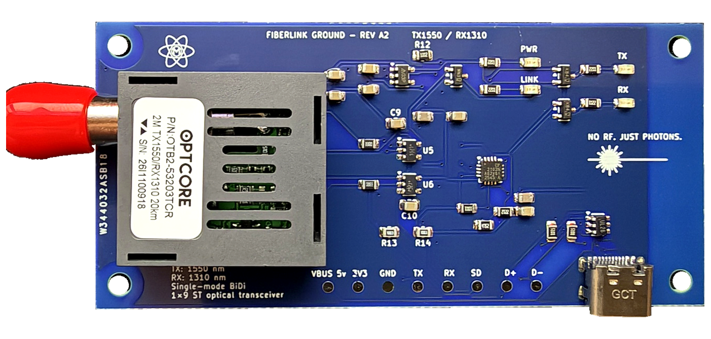
GROUND USB-C power + data

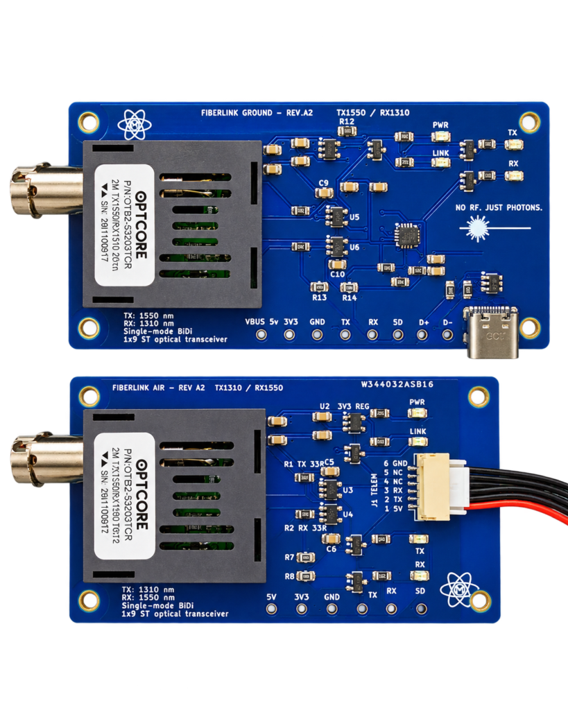
FiberLink Aero GROUND module
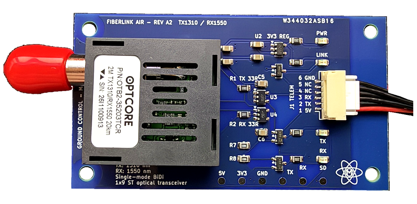
FiberLink Aero AIR module

AIR Autopilot powered

01

Single fiber

Bidirectional serial transport

02

5 V supply

Direct autopilot telemetry power

03

USB-C

Ground power + serial data

04

3.3 V UART

Autopilot logic interface

THE CONNECTION, SIMPLIFIED

A complete link.
Not a chain of adapters.

From the flight controller’s telemetry port to your ground-control application. One matched optical pair carries the existing serial data stream in both directions.

No separate battery-rail feed for the AIR board. No external USB-to-UART converter at the ground end.

PURPOSE-BUILT HARDWARE

Two modules. One matched system.

Compact, single-side populated boards with accessible mounting points and local status indicators.

AIR / REV A2

FiberLink Aero AIR module

Autopilot telemetry interface

01 / AIR MODULE

Powered directly
by your autopilot.

One compatible telemetry-port connection supplies the AIR board with 5 V power and 3.3 V UART data. No separate battery-rail power connection is required.

5 V telemetry power3.3 V UARTST optical port
Power and dataCombined telemetry connection
Optical pairingTX 1310 nm / RX 1550 nm
DiagnosticsPWR · LINK · TX · RX

02 / GROUND MODULE

USB-C power.
Integrated serial data.

Connect the GROUND module to your computer with USB-C. The same connection powers the board and presents the fiber link as a serial COM port, with USB-to-UART conversion built in.

USB-C power + dataSerial COM portST optical port
Host connectionUSB-C power and data
Optical pairingTX 1550 nm / RX 1310 nm
SetupSelect COM port + matching baud rate

GROUND / REV A2

FiberLink Aero GROUND module

USB-C host interface

ENGINEERING OVERVIEW

Interfaces.
Clearly defined.

Transparent, bidirectional UART transport for MAVLink command and telemetry data.

Confirm the autopilot’s connector pinout and available 5 V power budget. Configure matching serial baud rates at both ends.

InterfaceAIRGROUND
Electrical connectionAutopilot telemetry portUSB-C host connection
Power source5 V from compatible telemetry portUSB bus power
Serial interface3.3 V UART logicIntegrated USB-to-UART / COM
Optical connectionSingle-mode fiber / STSingle-mode fiber / ST
Transmit / receiveTX 1310 nm / RX 1550 nmTX 1550 nm / RX 1310 nm
Status indicatorsPWR / LINK / TX / RXPWR / LINK / TX / RX

FIBERLINK AERO / REV A2

Choose your hardware.

Start with a matched AIR + GROUND system, or ask about individual modules for your installation.

Confirm the required fiber, harnesses and accessories for your installation before ordering.

DOCUMENTATION

A closer look at the system.

PDF / REV A2

Product sheet

A concise overview of the AIR + GROUND system and its core interfaces.

PDF / REV A2

Technical overview

Module close-ups, power and data connections, and the optical link architecture.

SUPPORT & INTEGRATION

Software & design files.

Download published software packages, board CAD and enclosure STEP models. Check the listed compatibility before use.

SOFTWARE

Firmware & installers

Release packages, installation tools and supporting instructions.

No files published yet.

BOARD DESIGN

Board CAD files

Published AIR and GROUND board design and mechanical reference files.

No files published yet.

MECHANICAL

Enclosure STEP files

STEP models for enclosure fit, mounting and mechanical integration.

No files published yet.

INTEGRATION QUESTIONS

Know your connection.

Key details before you connect the hardware.

How does the AIR module get power?

The AIR module uses the 5 V supply from a compatible autopilot telemetry port. The same connector carries the UART data. Confirm the port pinout and available power budget before connecting the board.

Do I need a separate USB-to-UART adapter?

No. The GROUND module has USB-to-UART conversion built in. USB-C supplies power and provides the host connection. Select the assigned serial port in your ground-control application and match the autopilot baud rate. The appropriate USB-to-UART driver may be required by your computer.

Does the system need two fiber strands?

No. The matched AIR and GROUND optics use complementary transmit and receive wavelengths to carry serial data in both directions over a single strand of single-mode fiber, using ST connectors.

Can Rev A2 transport camera video or Ethernet?

Rev A2 is the UART / MAVLink interface shown here. Video and Ethernet transport are not included in this revision.

Is every autopilot telemetry port compatible?

Compatibility depends on the connector pinout, 5 V power supply and 3.3 V UART interface. Send the flight-controller model and the intended telemetry port before ordering when compatibility is uncertain.

BUILT BY MAKER MEHRER

Let’s connect
your next project.

For compatibility questions, quantity orders or custom integration, tell us your autopilot model and project requirements.